| Transitory, transtitorio. (Electrónica - Electronics ).
When a dc voltage is applied to a capacitor through a resistor, a current flows charging the capacitor (see Fig. 1a). Initially, all the voltage drops across the resistor; although current is flowing into the capacitor, there is no voltage drop across the capacitor. As the capacitor charges, the voltage across the capacitor builds up on an exponential, and the voltage across the resistor starts to decline, until eventually the capacitor is fully charged and current ceases to flow. The voltage across the capacitor is then equal to the supply voltage and the voltage across the resistor is zero. This is shown in Fig. 1b.
Two effects should be noted. The first is that the current flowing through the resistor and into the capacitor is the same for both components, but the volt- ages across each component is different, i.e., when the current flowing through the resistor is a maximum, the voltage across the resistor is maximum, given by E = IR, and the voltage is said to be in phase with the current. But in the case of the capacitor the voltage is zero when the current flowing is a maximum, and the voltage is a maximum when the current is zero. In this case the voltage lags the current or there is a phase shift between the voltage and the current of 90°. The second effect is that the voltage across the capacitor builds up at an exponential rate that is determined by the value of the resistor and the capacitor.
Similarly, if a dc voltage is applied to an inductance via a resistance as shown in Fig. 2a, the inductance will initially appear as a high impedance preventing current from flowing, so that the current will be zero, the supply voltage will appear across the inductance, and there will be zero voltage across the resistor. After the initial turn-on, current will start to flow and build up. The voltage across the resistor increases and starts to decrease across the inductance allowing the current to build up exponentially, until the current flow is limited by the resistance at its maximum value and the voltage across the inductance is zero. This is shown in Fig. 2b. The effects are similar in that the same current is flowing in both devices, the voltage and current in the resistor are in phase, but in the inductor are out of phase, i.e., in this case the voltage appears across the inductance before the current starts to flow, and goes to zero when the current is at its maximum, so that the voltage leads the current, and there is a phase shift between the voltage and the current of 90°. The voltage across the resistor increases at an exponential rate that is determined by the value of the inductance and resistance.
Cuando se aplica un voltaje de CC a un capacitor a través de una resistencia, fluye una corriente que carga el capacitor (vea la figura 1a). Inicialmente, todo el voltaje cae a través de la resistencia; aunque la corriente fluye hacia el capacitor, no hay caída de voltaje a través del capacitor. A medida que el capacitor se carga, el voltaje a través del capacitor aumenta exponencialmente y el voltaje a través de la resistencia comienza a disminuir, hasta que finalmente el capacitor está completamente cargado y la corriente deja de fluir. El voltaje a través del capacitor es entonces igual al voltaje de alimentación y el voltaje a través de la resistencia es cero. Esto se muestra en la Figura 1b.
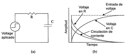
Fig. 1 - Para demostrar el transitorio de entrada: (a) circuito con resistencia y capacitancia y (b) formas de onda asociadas.
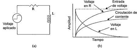
Fig. 2 - Para demostrar el transitorio de entrada: (a) circuito con resistencia y capacitancia y (b) formas de onda asociadas.
Cabe señalar dos efectos. La primera es que la corriente que fluye a través de la resistencia y hacia el capacitor es la misma para ambos componentes, pero los voltajes en cada componente son diferentes, es decir, cuando la corriente que fluye a través de la resistencia es máxima, la tensión a través de la resistencia es máxima , dado por E = IR, y se dice que el voltaje está en fase con la corriente. Pero en el caso del condensador, el voltaje es cero cuando la corriente que fluye es máxima, y el voltaje es máximo cuando la corriente es cero. En este caso, la el voltaje queda retrasado con respecto a la corriente o hay un cambio de fase entre el voltaje y la corriente de 90 °. El segundo efecto es que el voltaje a través del capacitor se eleva a una tasa exponencial que está determinada por el valor de la resistencia y el capacitor.
De manera similar, si se aplica un voltaje de CC a una inductancia a través de una resistencia como se muestra en la Fig.2a, la inductancia será vista inicialmente como una impedancia alta que evita que la corriente fluya, de modo que la corriente será cero, el voltaje de alimentación se elevará a través del inductancia, y habrá cero voltaje en los extremos de la resistencia. Después de la conexión inicial, la corriente comenzará a fluir y elevarse. El voltaje en los extremos de la resistencia aumenta y comienza a disminuir a través de la inductancia, lo que permite que la corriente se eleve exponencialmente, hasta que el flujo de corriente esté limitado por la resistencia en su valor máximo y el voltaje a través de la inductancia sea cero. Esto se muestra en la Figura 2b. Los efectos son similares en que la misma corriente fluye en ambos dispositivos, el voltaje y la corriente en la resistencia están en fase, pero en el inductor están desfasados, es decir, en este caso, el voltaje se forma en los extremos de la inductancia antes de que la corriente comience a fluir, y cae a cero cuando la corriente está en su valor máximo, de modo que el voltaje se adelanta a la corriente, y hay un cambio de fase o desfasaje entre el voltaje y la corriente de 90 °. El voltaje a través de la resistencia aumenta a una tasa exponencial que está determinada por el valor de la inductancia y la resistencia. |