| RTD. Resistance temperature devices, (Electrónica - Electronics ) dispositivos de temperatura de resistencia.
Resistance temperature devices (RTD) are either a metal film deposited on a former or are wire-wound resistors. The devices are then sealed in a glass- ceramic composite material. The electrical resistance of pure metals is positive, increasing linearly with temperature. Table 1 gives the temperature coefficient of resistance of some common metals used in resistance thermometers. These devices are accurate and can be used to measure temperatures from -300 to 1400°F (-170 to 780°C).
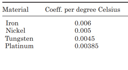
Table 1. Temperature Coefficient of Resistance of Some Common Metals
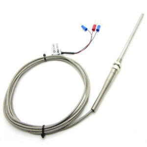
Figure : RTD sensor
In a resistance thermometer the variation of resistance with temperature is given by
RT2 = RT1 (1 + Coeff. [T2 - T1])
where RT2 is the resistance at temperature T2 and RT1 is the resistance at temperature T1.
Resistance devices are normally measured using a Wheatstone bridge type of system, but are supplied from a constant current source. Care should also be taken to prevent electrical current from heating the device and causing erroneous readings. One method of overcoming this problem is to use a pulse technique. When using this method the current is turned ON for say 10 ms every 10 s, and the sensor resistance is measured during this 10 ms time period. This reduces the internal heating effects by 1000 to 1 or the internal heating error by this factor.
Dispositivos de temperatura de resistencia
Los dispositivos de temperatura de resistencia (RTD) están formados por una película de metal depositada sobre un molde o son resistencias de alambre enrollado. Los dispositivos luego se sellan dentro de un material compuesto vitrocerámico. La resistencia eléctrica de los metales puros es positiva y aumenta linealmente con la temperatura. La Tabla 1 da el coeficiente de temperatura de resistencia de algunos metales comunes usados en termómetros de resistencia. Estos dispositivos son precisos y se pueden utilizar para medir temperaturas de -300 a 1400 °F (-170 a 780 °C).
| Material |
Coeficiente por Grados Celsius |
| Hierro |
0.006 |
| Níquel |
0.005 |
| Tungsteno |
0.0045 |
| Platino |
0.00385 |
Tabla 1- Coeficiente de temperatura de resistencia de algunos metales comunes
En un termómetro de resistencia, la variación de la resistencia con la temperatura está dada por
RT2 = RT1 (1 + coeficiente [T2 - T1])
donde RT2 es la resistencia a la temperatura T2 y RT1 es la resistencia a la temperatura T1.
Los dispositivos de resistencia se miden normalmente utilizando un sistema tipo puente de Wheatstone, pero se alimentan con una fuente de corriente constante. Se debe tener cuidado de evitar que la corriente eléctrica caliente el dispositivo y provoque lecturas erróneas. Un método para superar este problema es utilizar una técnica de impulsos. Cuando se utiliza este método, la corriente se activa durante, por ejemplo, 10 ms cada 10 s, y la resistencia del sensor se mide durante este período de tiempo de 10 ms. Esto reduce los efectos del calentamiento interno en 1000 a 1 o el error de calentamiento interno por este factor.
Resistive temperature detectors (RTD) measure the change in the electrical resistance of a wire-wound resistor with temperature, typically, a platinum resistance element is used with a resistance of about 100 Ω. The resistance change can be measured in a bridge circuit, but normally the resistor is driven from a constant current source and the voltage developed across the resistor measured. Care must be taken with these devices to ensure that the current flowing through the devices is low to minimize the temperature changes occurring due to the internal heating of the resistor. Pulse techniques can be used to prevent internal heating. In this case the current is turned on for a few milliseconds, the voltage measured and then turned off for, say, a second. Next figure (a) shows the simplest connection to the RTD with just two leads, the meter being connected to the current supply leads. The resistance of long leads between the detector and the resistor contribute to measurement error, as the meter is measuring the voltage drop across the current lead resistance and junctions as well as the RTD.
Figure (b) shows a 4-wire connection to an RTD. The meter connects directly to the RTD so that only the voltage drop across the RTD is measured; no error is introduced due to the resistance of the current supply contacts or lead resistance to the RTD. Platinum is the material of choice for an RTD. A linearity of 3.6 percent can be obtained from 0 to 850°C without signal conditioning.
The RTD has a constant current flowing through it giving an offset zero, so that zero level correction and span conditioning are required.
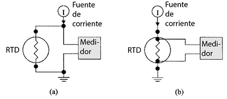
Fig- RTD connections using (a) common supply and meter leads and (b) directly connected meter. - Conexiones RTD utilizando (a) cables comunes de suministro y medidor y (b) medidor conectado directamente. -
Los detectores de temperatura resistivos (RTD) miden el cambio en la resistencia eléctrica de una resistencia de alambre bobinado con la temperatura; por lo general, se usa un elemento de resistencia de platino con una resistencia de aproximadamente 100 Ω. El cambio de resistencia se puede medir en un circuito de puente, pero normalmente la resistencia se acciona desde una fuente de corriente constante y se mide el voltaje desarrollado a través de la resistencia. Se debe tener cuidado con estos dispositivos para asegurarse de que la corriente que fluye a través de los dispositivos sea baja para minimizar los cambios de temperatura que ocurren debido al calentamiento interno de la resistencia. Las técnicas de pulso se pueden utilizar para evitar el calentamiento interno. En este caso, la corriente se activa durante unos pocos milisegundos, el voltaje se mide y luego se desactiva durante, digamos, un segundo. La figura (a) anterior muestra la conexión más simple al RTD con solo dos cables, el medidor está conectado a los cables de suministro de corriente. La resistencia de los cables largos entre el detector y la resistencia contribuye al error de medición, ya que el medidor mide la caída de voltaje a través de la resistencia y las uniones del cable de corriente, así como también en el RTD.
La Figura (b) muestra una conexión de 4 hilos a un RTD. El medidor se conecta directamente al RTD para que solo se mida la caída de voltaje en el RTD; no se introduce ningún error debido a la resistencia de los contactos de suministro de corriente o la resistencia del cable al RTD. El platino es el material elegido para un RTD. Se puede obtener una linealidad del 3,6 por ciento de 0 a 850 °C sin acondicionamiento de señal.
El RTD tiene una corriente constante que fluye a través del mismo, dando un desplazamiento de cero, por lo que se requiere la corrección del nivel cero y el acondicionamiento de rango.
Resistance temperature devices (RTD) can be connected directly to the controller peripheral amplifiers using a two, three, or four wire lead configuration; these are shown in next figure. The RTD is driven from a constant current source I and the voltage drop across the RTD measured. The two wire connection (a) is the simplest and cheapest, the three wire connection (b) is a compromise between cost and accuracy, and the fourwire connection (c) is the most expensive but most accurate. The wires in all cases will be in screened cables.
In the case of the two wire connection the voltage drop is measured across the lead wires as well as the RTD; the resistance in the two lead wires can be significant, giving a relatively high degree of error.
In the case of the three wire connection, a direct return lead from the RTD to the voltmeter is added, as shown. The voltage drop δV between the ground connection and the lower RTD connection as well as the voltage drop V between the current source and the lower RTD connection can be measured. If the resistance in each supply lead to the RTD is assumed to be the same, the voltage across the RTD is V - δV correcting for the error caused by the common lead wire. In most cases each lead wire will have about the same resistance, so this method is accurate enough for most applications. With the fourwire connection the voltmeter is connected directly to the RTD as shown in Fig. (c) and because no current flows in the leads to the voltmeter there is no voltage drop in the measuring leads and an accurate RTD voltage reading is obtained.
.jpg)
Fig. Alternative connection schemes between an RTD and a controller (a) two lead, (b) three
lead, and (c) four lead. Esquemas de conexión alternativos entre un RTD y un controlador de procesos (a) dos conductores, (b) tres conductores y (c) cuatro conductores.
Los dispositivos sensores de temperatura de resistencia (RTD) se pueden conectar directamente a los amplificadores periféricos del controlador de procesos mediante una configuración de dos, tres o cuatro cables; estos se muestran en la Fig. siguiente. El RTD es controlado por una fuente de corriente constante I que mide la caída de voltaje a través del mismo. La conexión de dos cables (a) es la más simple y económica, la conexión de tres cables (b) es un compromiso entre el costo y la precisión, y la conexión de cuatro cables (c) es la más cara pero la más precisa. Los conductores en todos los casos estarán formando cables apantallados.
En el caso de la conexión de dos cables, la caída de voltaje se mide entre los cables conductores y el RTD; la resistencia en los cables de dos conductores puede ser significativa, dando un grado de error relativamente alto.
En el caso de la conexión de tres cables, se agrega un cable de retorno directo desde el RTD al voltímetro, como se muestra en la figura. Se puede medir la caída de voltaje δ
V entre la conexión a tierra y la conexión inferior del RTD, así como la caída de voltaje V entre la fuente de corriente y la conexión inferior del RTD. Si se supone que la resistencia en cada cable de alimentación al RTD es la misma, el voltaje a través del RTD es V - δ
V corrigiendo el error causado por el cable conductor común. En la mayoría de los casos, cada cable tendrá aproximadamente la misma resistencia, por lo que este método es lo suficientemente preciso para la mayoría de las aplicaciones. Con la conexión de cuatro cables, el voltímetro se conecta directamente al RTD como se muestra en la figura (c) y debido a que no fluye corriente en los cables al voltímetro, no hay caída de voltaje en los cables de medición y se obtiene una lectura de voltaje RTD precisa. |


